- 1. Introduction
- 2. Calibration Effects
- 3. Methodology
- 4. Supported Accuracy
- 5. Calibration Tools
- 6. Calibration in ISO/IEC 17025 certified laboratory
1. Introduction
The 3-point user calibration mechanism supported by Dracal products whose product code ends with "-CAL". In a sensor supporting user calibration, only the real channels are directly calibratable. The virtual channels, whose values are calculated from the real channels, are however indirectly affected by the calibration applied to the channels from which they are calculated.
The user calibration mechanism supports up to 3-point calibration. However, the user is free to calibrate its device in only 1 or 2 points (or even not at all!) if desired. By "calibration point" we mean the association of a value measured by the instrument with its calibration value. The calibration function is polynomial and exact at the calibration points. Calibration points are recorded directly in the device firmware so that a calibrated instrument will remain calibrated regardless of the tool used to access its readings.
All calibration points are of equal importance. The order in which the points are entered has no effect on the calibration calculation.
2. Calibration Effects
The purpose of calibration is to introduce a correction to the measurement read by a sensor, based on the measurement of a reference device called a "standard". There are several types of calibration functions, which we can divide into two categories: linear or non-linear. The calibration function supported by Dracal Technologies products is of polynomial type. This is equivalent to a linear calibration in the case of a 1-point or 2-point calibration. For a 3-point calibration, the polynomial calibration is non-linear and offers the advantage of being accurate at all three calibration points. In the following paragraphs, we illustrate the effect of polynomial calibration according to the number of points entered by the user. The different illustrations are based on a fictitious measurement curve in order to clearly visualize the various calibration effects.
2.1. 1-Point Calibration
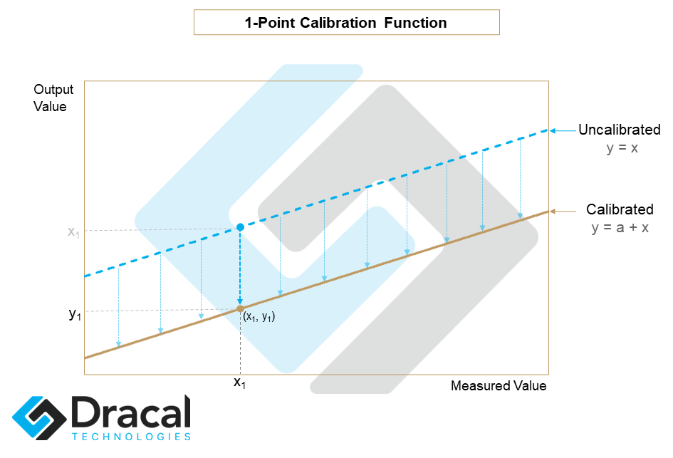
By one-point calibration, we mean the recording of a point (x1,y1 ) where x1 is the direct measurement of the sensor and y1 is the calibration value we wish to impose. A calibration point can therefore be schematically represented as a correspondence x1 -> y1. The effect of the calibration at one point is to apply a constant offset to all the measurements returned by the instrument. The calibration function for a 1-point calibration then has the following form: y = a+x. It is easily established that the value of this offset is: a = y1- x1. The calibration function for 1-point calibration is illustrated below:
The effect of such a calibration on a measurement curve is illustrated below:
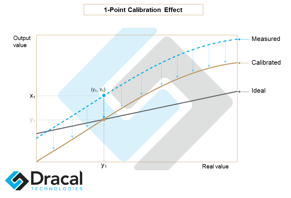
In a 1-point calibration, the point to be calibrated x1 should be approximately at the center of the user's intended measurement spectrum. For example, a user wishing to measure temperatures between 15 ℃ and 25 ℃ should not calibrate at the same point as a user wishing to measure temperatures between 20 ℃ and 70 ℃.
2.2. 2-Point Calibration
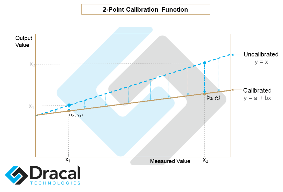
A two-point calibration is carried out by recording two correspondences: (x1,y1) and (x2,y2) and performs a linear correction. The calibration function then has the following form: y = a+bx This is illustrated in the following image:
The effect of such a calibration on a measurement curve is illustrated below:
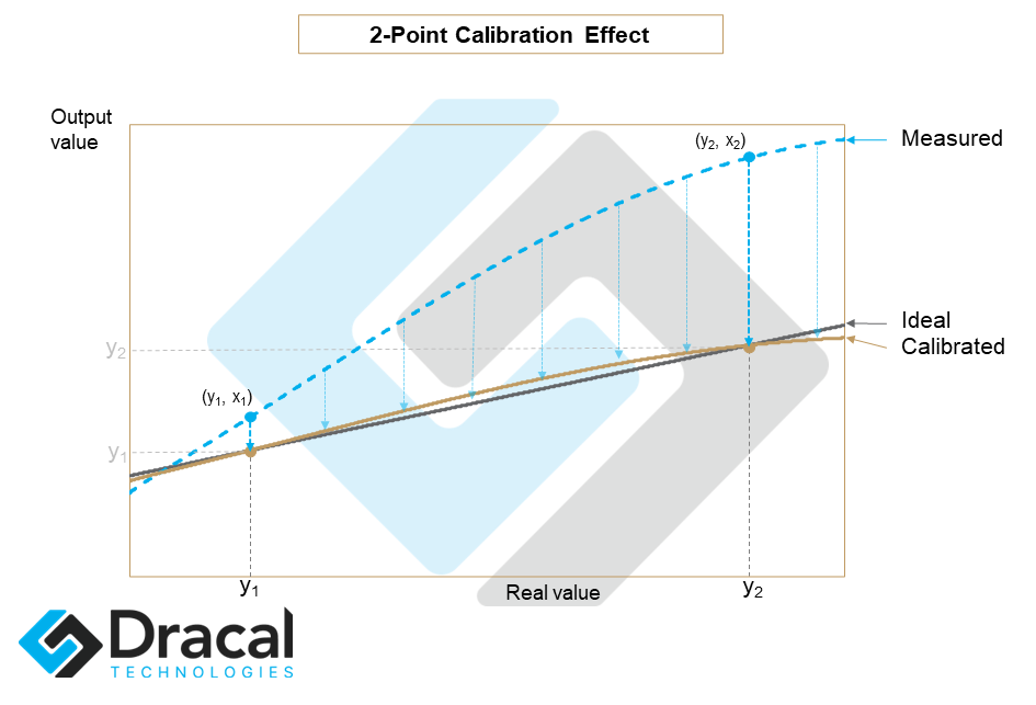
In a 2-point calibration, the points to be calibrated should be near the extremes of the measurement spectrum expected by the user.
2.3. 3-Point Calibration
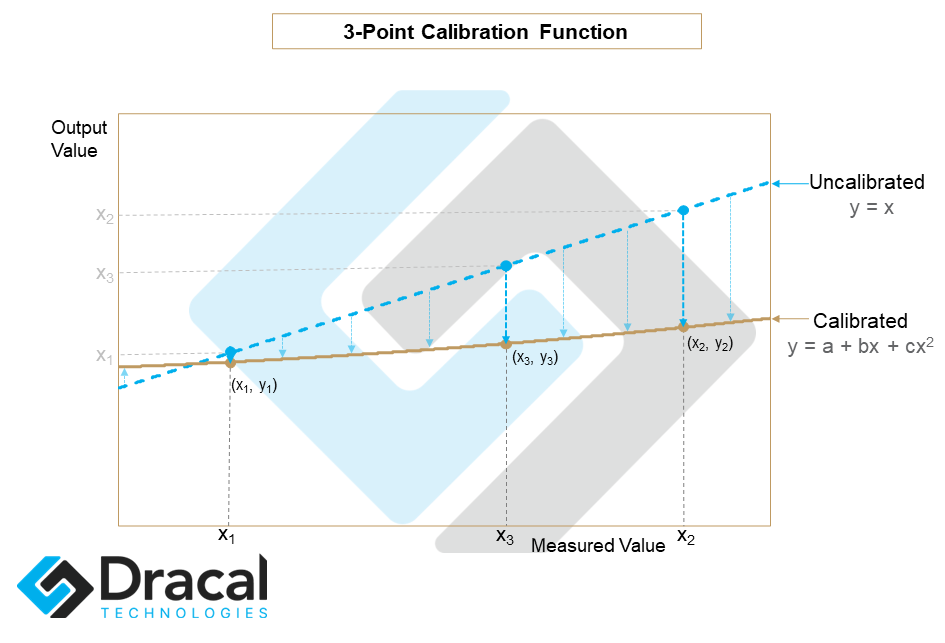
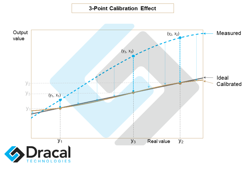
Finally, a 3-point calibration applies a degree 2 polynomial correction of the form y = a + bx + cx2. The coefficients a, b and c are calculated so that at calibration points x1, x2 and x3, the values returned by the calibration are exactly y1, y2 and y3 respectively. With this definition, the coefficients a, b and c are uniquely defined. The image below illustrates a possible 3-point calibration function:
The effect of such a calibration on a measurement curve is illustrated below:
In a 3-point calibration, two of the points to be calibrated should be near the extremes of the user's predicted measurement spectrum, while the other should approximately lie in the center of the spectrum. The image below illustrates the importance of choosing calibration points so that they cover the expected operating range (not the theoretical range) of the instrument.
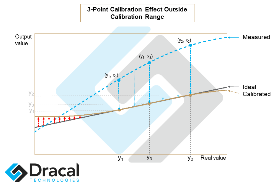
We can see from this example that although the calibration has considerably improved the accuracy of the measurement between the calibration points, it has deteriorated in the far left range away from the calibration points.
3. Methodology
The application of calibration is a double-edged sword. When done correctly, calibration offers a powerful and very practical tool. However, when improperly programmed, calibration becomes harmful and can potentially invalidate experimental results for a very long time, that is the time it takes before one realizes that an error has been produced during its implementation.
The adoption of the following basic principles will considerably limit the risk of errors and allow a confident use of the calibration tool at your disposal.
3.1. If possible, sample before calibrating
Before calibrating at a given point, if possible, take the time to compare the difference between the measured and theoretical values for a few points before and after the target measurement, in order to limit the risks of integrating noise errors in a calibration measurement.
3.2. Adapt the calibration points to the operating range of the instrument
Wherever possible, select calibration points so that they are centered and cover the planned operating range of the instrument.
3.3. Define the calibration points from the raw measurements of the instrument
The risk here is to define a calibration point when some calibration points are already active. For example, one could imagine that someone is performing a one-point calibration. Then, letting some time pass, uses the calibrated data to determine an adjustment to the calibration already present (adding points, changing points, etc.). However, such a modification could only distort subsequent measurements since a calibration point must absolutely be established from the raw measurements of the instrument.
Therefore, before collecting data to determine your calibration points, it is crucial to check whether a calibration is already active and if so, to deactivate it, even if only for the time of your calibration measurements.
4. Supported Accuracy
By definition, calibration is performed by adjustment calculations applied to the raw readings. The accuracy of the calibration calculations performed by Dracal products is accurate to 6 significant digits or more. That being said, it goes without saying that the accuracy of a calculation could not exceed the accuracy of the sensor itself. Therefore, when choosing the number of decimal places to be displayed, it should be based on the actual accuracy of the raw measurement and not on the number of display decimal places available.
5. Calibration Tools
Dracal Technologies provides you with two free tools to calibrate your Dracal instruments supporting calibration: DracalView and dracal-usb-cal.
DracalView is our free data acquisition and recording software. All the functionalities necessary for calibration have been implemented in version v2.1.21 and following of DracalView. Consult this specific section of the complete documentation of DracalView to learn how to calibrate your device in all simplicity.
dracal-usb-cal is a command line tool developed specifically to calibrate your devices from a terminal. See the complete documentation of dracal-usb-cal to familiarize yourself with the tool. Access to your sensors via a command line tool gives you the possibility to easily integrate our products into your own software.
6. Calibration in ISO/IEC 17025 certified laboratory
If your product is equipped with the user calibration mechanism, Dracal Technologies offers you the possibility to have your instrument calibrated (in a maximum of 3 points per real channel) and certified in an ISO/IEC 17025 certified laboratory. You will find on this page information about the traceability certificates issued by the laboratory. To determine if your device is eligible for ISO/IEC 17025 certified laboratory calibration, go to the "Order" page of your product and check if traceable certificates are available for it.