How to read RTD sensors in LabVIEW in 5 simple steps
RTD and PT100 sensors
Resistance Temperature Detectors (RTDs) are widely regarded for their precision and reliability in temperature measurement, making them a preferred choice in industries where accurate thermal readings are critical. Unlike thermocouples, which measure voltage to determine temperature, RTDs rely on the predictable change in electrical resistance of a metal—typically platinum—relative to temperature. The PT100, a popular RTD, has a resistance of 100 ohms at 0°C and offers precise temperature readings across a broad range. This stability and accuracy make RTD temperature probes indispensable in applications like industrial process control, laboratory experiments, and environmental monitoring, where even slight temperature variations can have significant consequences.
Dracal USB adapters for RTD PT100 sensors
Dracal Technologies’ RTD-series USB adapters provide a reliable and straightforward solution for connecting PT100 RTD sensors to your system. For added precision, customers can choose the optional user-calibration feature, enabling them to adjust the device to their specific requirements and achieve optimal accuracy. Additionally, an optional Virtual COM protocol feature allows for seamless integration with a wide range of platforms, ensuring flexible data communication. These affordable adapters also come with free, easy-to-use data logging software and a comprehensive set of code examples for quick integration into systems such as LabVIEW, Python, C++, and more.


What will your set-up be?
- The two rows represent the 2 possible operational mode of our instruments, which is USB or VCP. Instruments in USB mode have to be querried by our free command-line tools, while those with VCP mode can be querried directly from the instrument, without the need of our free, but proprietary, tools.
- The two columns represent the way to connect the instrument to the PC, which is either directly via a USB port on your PC, or wirelessly (Wi-Fi/Ethernet) using our SensGate gateway.
|
PC-connected |
Wi-Fi/Ethernet-connected |
|
|
USB |
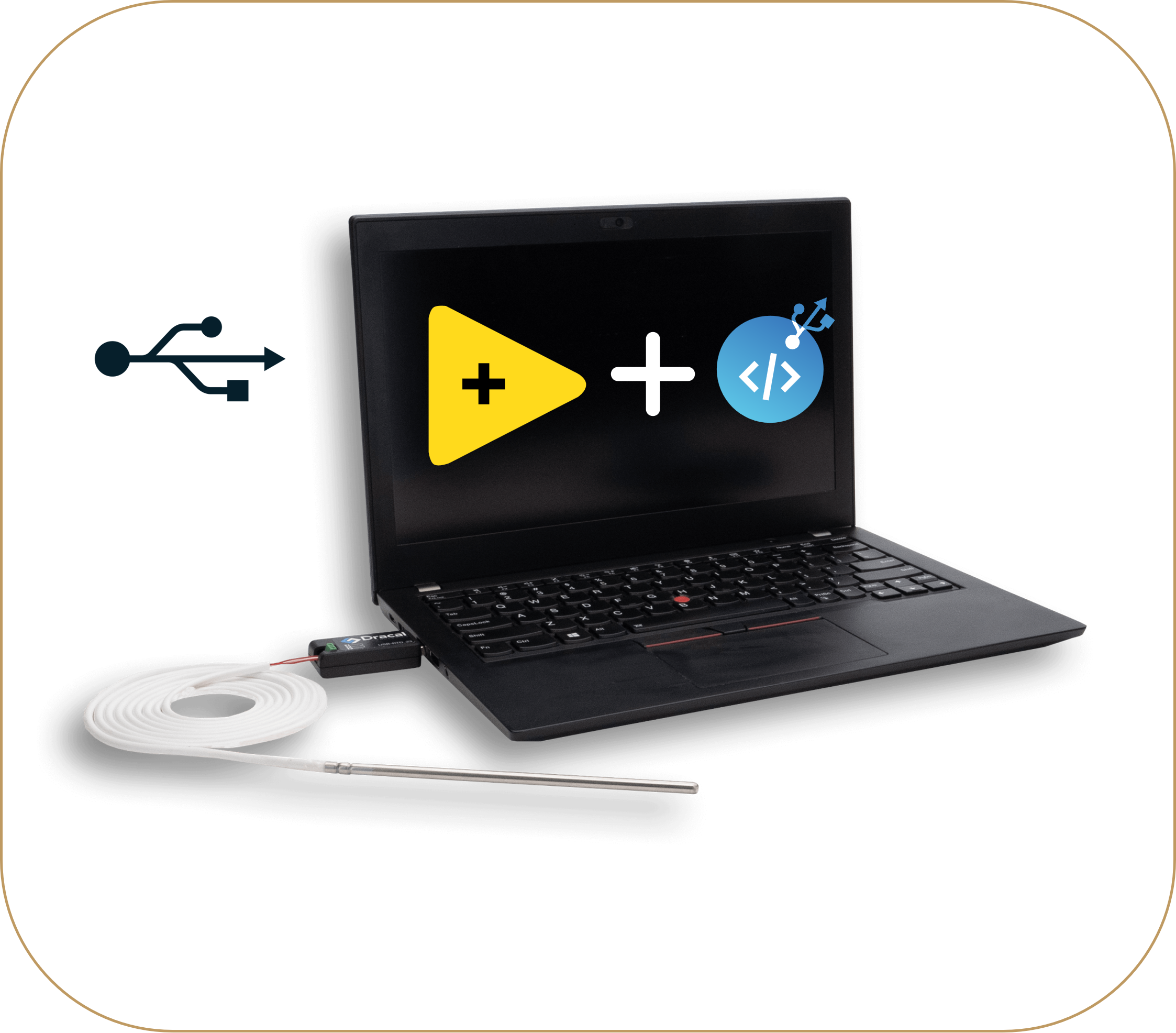
CONFIGURATION 1
RTD adapters physically connected to a PC via USB and systems that can invoke our free command-line tools. |
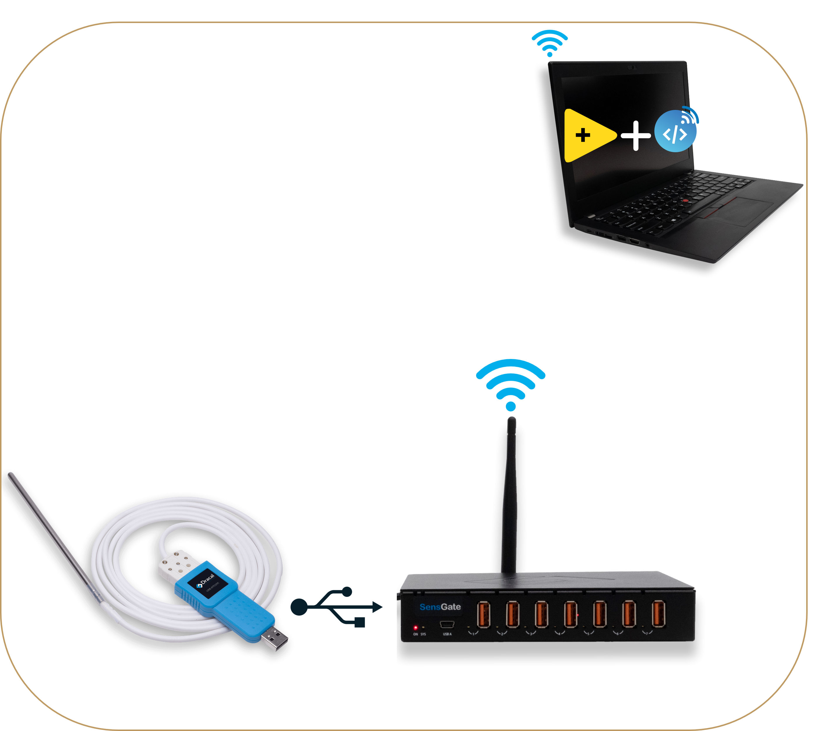
CONFIGURATION 3
Dracal RTD adapters that connect wirelessly to a PC via a SensGate and systems that can invoke our free command-line tools. |
|
COM |
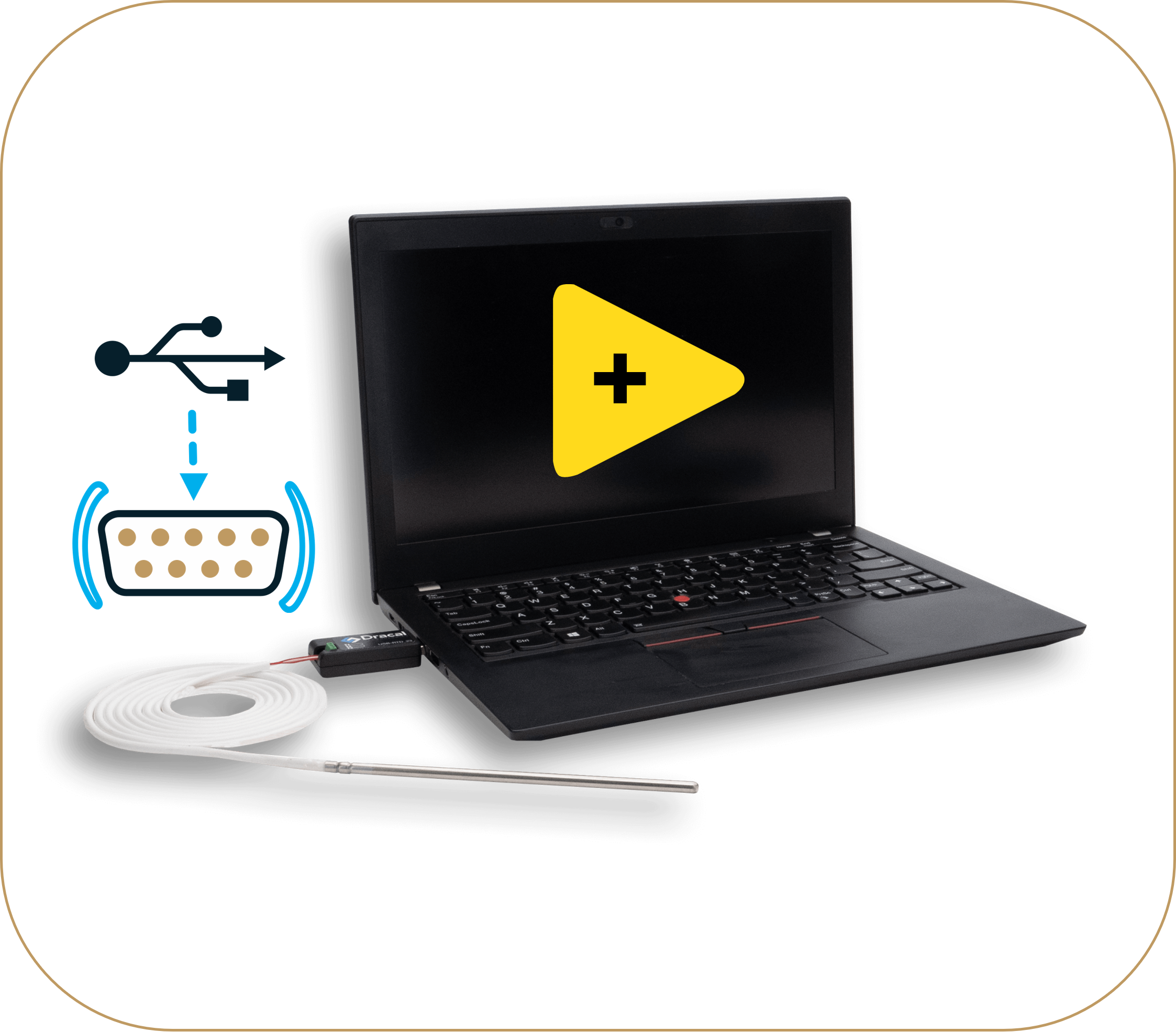
CONFIGURATION 2
RTD adapters physically connected to a PC via USB and systems that prefer to talk directly to the device via the COM protocol. |
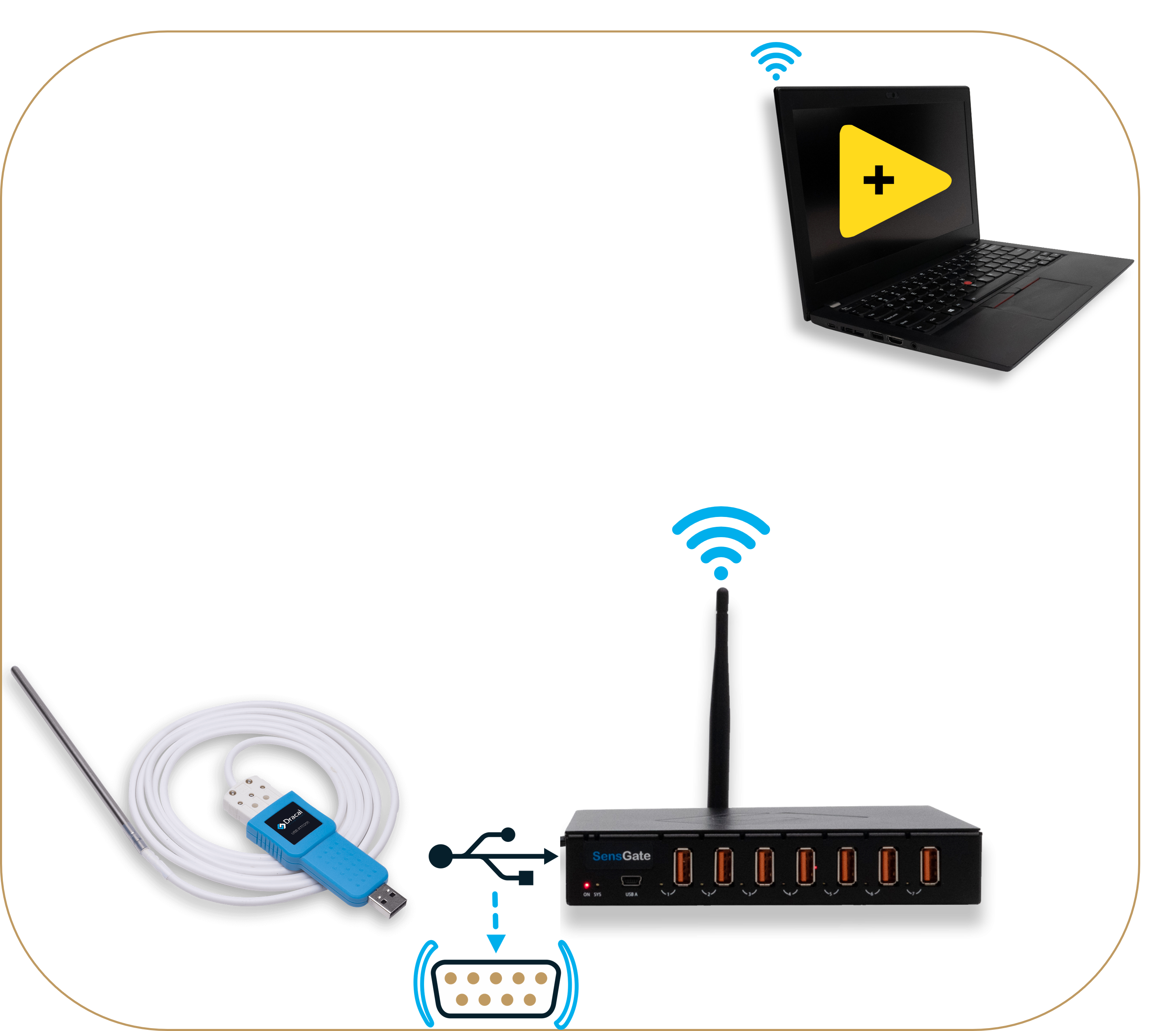
CONFIGURATION 4
Dracal RTD adapters that connect wirelessly to a PC via a SensGate and systems that prefer to talk directly to the device via the COM protocol. |
Step 1. Get your equipment
Whichever your set-up, you will need the following three elements:
- 1 X PC (Windows, Mac or Linux) with LabVIEW installed
- 1 X RTD PT100 sensor (from Dracal or your own)
- 1 X Dracal RTD-series adapter
Additional equipment/option for your specific set-up is:
|
PC-connected |
Wi-Fi/Ethernet-connected |
|
|
USB |
CONFIGURATION 1
|
CONFIGURATION 3
|
|
COM |
2)
|
4)
|
Step 2. Download the free DracalView software & tools
Download the DracalView toolbox that includes the DracalView GUI as well as the command-line tools. When you will receive your RTD adapter, you will then be ready to connect your RTD PT100 probe and use the DracalView GUI to quickly visualize your RTD readings. For models that are calibratable, calibration can also be intuitively performed with DracalView.
Step 3. Switch your sensor to Virtual COM mode (configs. 2 & 4 only)
* For more information on VCP, consult the complete VCP documentation.
For users that chose to work in virtual COM mode, switch your device from USB to VCP mode. This is done via our command line tool dracal-usb-set. To do this, execute the command set_protocol VCP followed by the the reset command to create a virtual device disconnection. In the following example, this procedure is illustrated on a device whose serial number is E16026.
C:Program Files (x86)DracalView>  dracal-usb-set -s E16026 set_protocol VCP
C:Program Files (x86)DracalView>  dracal-usb-set -s E16026 reset
If only one Dracal sensor is connected to your computer when executing these commands, you can omit to specify the serial number of your device (as there is only one) by using the option -f as in the following example:
C:Program Files (x86)DracalView>  dracal-usb-set -f set_protocol VCP
C:Program Files (x86)DracalView>  dracal-usb-set -f reset
Note for Windows users: When executing the command reset, the following echo will be returned in your terminal:
C:Program Files (x86)DracalView>  dracal-usb-set -f reset
USB control message error: usb_control_msg: sending control message failed, win error: The device does not recognize the command.
This behaviour is normal and confirms that the disconnection was successfully completed.
Step 4. Connect the SensGate to your network (configs. 3 & 4 only)
Step-by-step procedure to connect your SensGate to an existing network here. If you prefer to create your own sub-network for your project, follow this step.
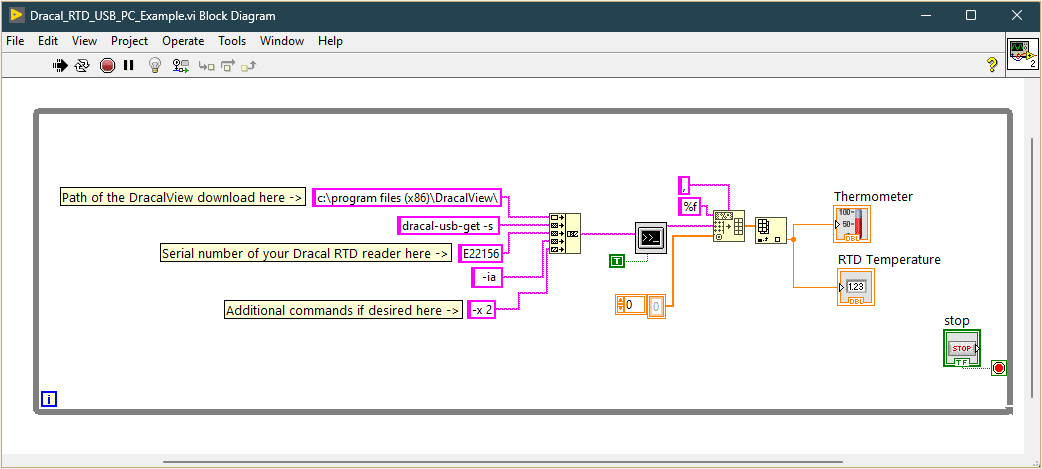
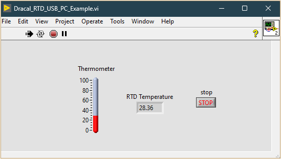
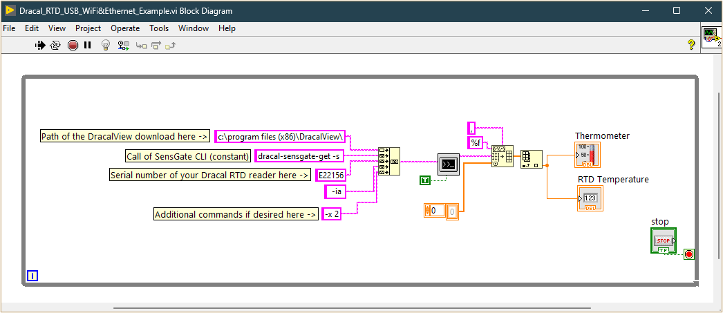
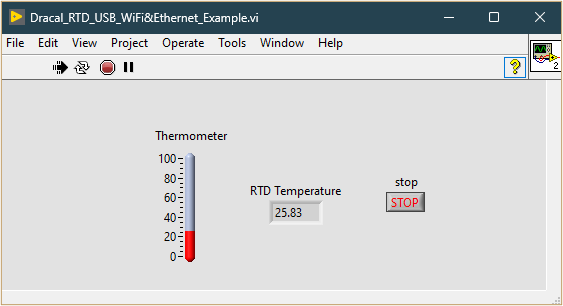
Step 5. Download and run your ready-made LabVIEW model
Each of the above configurations is associated with a downloadable template in the table below. Click on the images to enlarge them and get a better view of the block diagram and main window of the proposed template.
Models for configurations 1 & 3 leverage Dracal's command line tools, ideal for Dracal adapters connected via USB either to the computer or, with some minor adjustments, to a SensGate (Wi-Fi/Wireless gateway). This solution is for instruments without the virtual COM protocol option. This method is simple and effective, allowing LabVIEW to directly access sensor data using preconfigured commands that retrieve real-time measurements. With these tools, users can easily integrate temperature readings into their LabVIEW project within minutes.
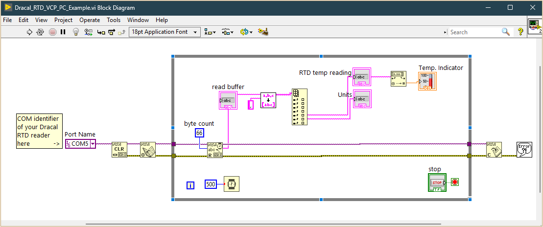
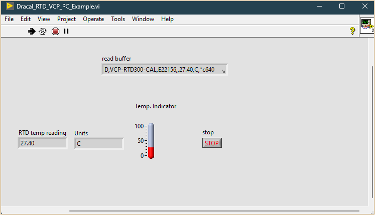
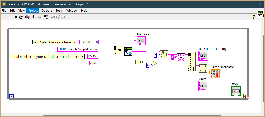
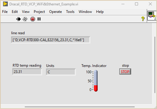
For users who have opted for the serial protocol, the models for configurations 2 and 4 offer a different approach, communicating with the RTD adapter via a virtual serial port. In model for configuration 2, the VISA (Virtual Instrument Software Architecture) functions built into LabVIEW make this integration straightforward, facilitating direct read/write commands to the sensor. This model gives users better control over data acquisition and allows for more advanced customization in LabVIEW. In model 4 for Wi-Fi/Ethernet connectivity, the REST API available in SensGate enables direct access to your sensor data via an HTTP block.
|
PC-connected |
Wi-Fi/Ethernet-connected |
|
|
USB |
CONFIGURATION 1
|
CONFIGURATION 3
|
|
COM |
CONFIGURATION 2
|
CONFIGURATION 4
|
Conclusion
As you can see, getting RTD PT100 sensor data into LabVIEW is a matter of a few minutes. All methods are supported by Dracal’s extensive library of code examples, ensuring a smooth integration experience, regardless of the communication protocol (USB vs VCP) or the connection type (USB vs Wi-Fi/Ethernet) chosen.